Sheet Metal Factory Prototyping Explained: From CAD to Production-Ready Parts
- Share
- Issue Time
- Aug 22,2026
Summary
This comprehensive guide explores the critical process of sheet metal prototyping, highlighting its importance in bridging the gap between design concepts and tangible products. Prototyping serves as an essential first step in manufacturing, enabling the validation of designs, early identification of flaws, and significant reduction in costs and risks before committing to large-scale production. The article emphasizes that a physical prototype offers insights into fit, form, and function that di
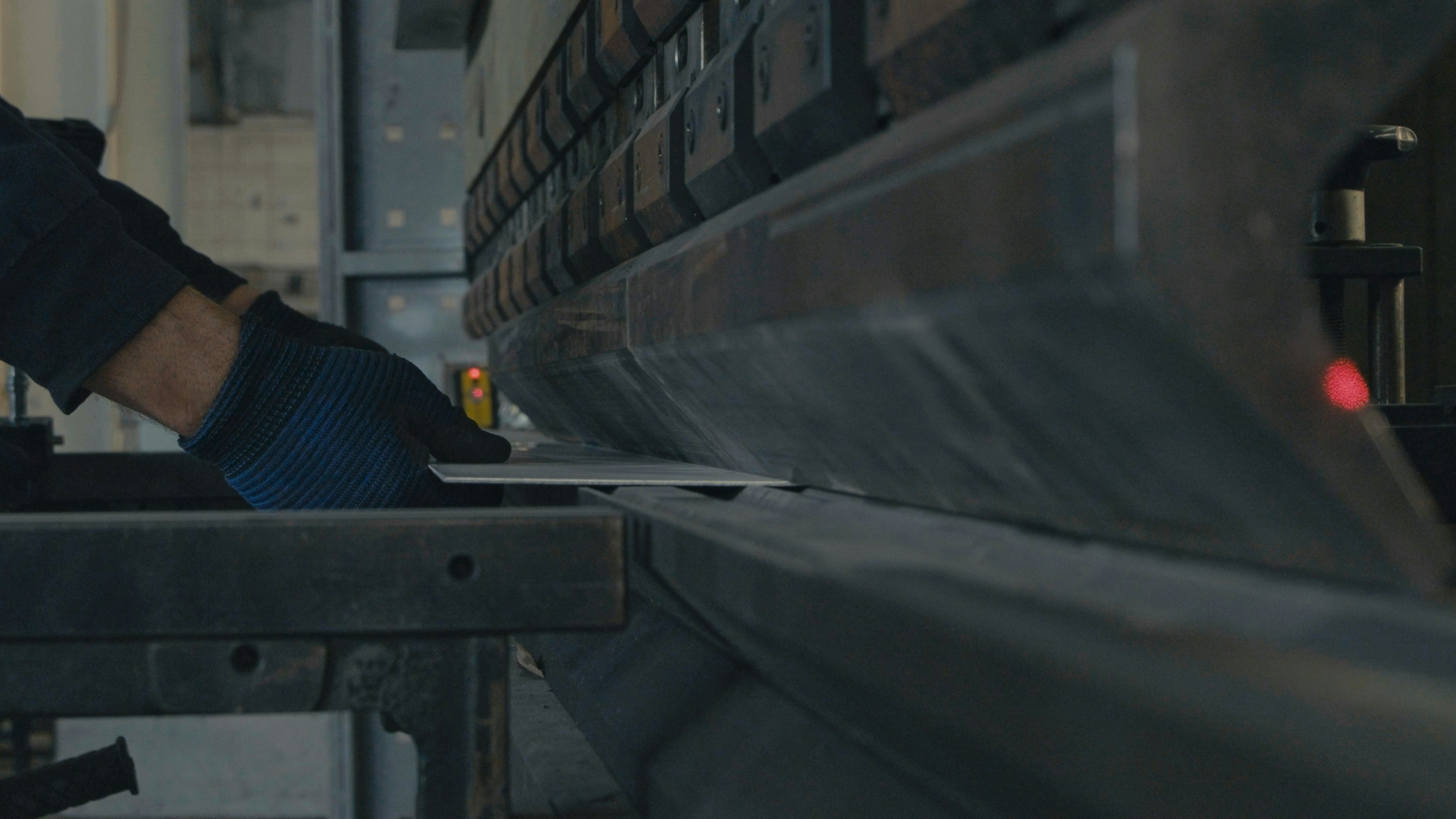
We've all seen incredible products, but few people think about the journey they take from an idea in someone's head to a tangible item. For us, in the world of manufacturing, especially with sheet metal, prototyping is that critical first step that brings concepts to life. This journey, from a complex CAD model to a fully production-ready part, requires careful planning and precise execution. It's where we test our ideas, identify potential issues, and refine designs before committing to large-scale production.
Today, we're going to pull back the curtain and talk about the vital considerations we face when creating sheet metal prototypes, sharing insights on how to get it right the first time and work effectively with a sheet metal factory. This guide will walk you through everything from the conceptual foundation to advanced manufacturing techniques, ensuring your next project is a resounding success.
Key Takeaways
- Prototyping Validates Designs: A physical prototype is the ultimate test of a CAD model, allowing you to check for fit, form, and function. It transforms theoretical designs into tangible models, revealing flaws that are not apparent in digital simulations. This step is crucial for verifying geometry, interfaces, and structural integrity before mass production.
- Early Iteration Reduces Costs and Risks: Prototyping allows for rapid and cost-effective design iterations. Identifying and fixing design flaws, such as hole misalignments or bend deformations, during the prototype phase is significantly cheaper than correcting them after production tooling is complete. This iterative process of testing, analyzing, and refining helps in achieving a better final product.
- Collaboration with a Fabricator is Key: A sheet metal factory is more than a vendor; they are a partner in development. Their expertise in materials and Design for Manufacturability (DFM) can optimize your design for efficiency, reduce costs, and avoid downstream issues. Clear communication and detailed feedback are essential for a successful partnership.
- Material and Process Selection are Foundational: The choice of material—be it steel, aluminum, or stainless steel—directly impacts the prototype's strength, weight, corrosion resistance, and cost. Similarly, understanding the manufacturing processes, like laser cutting or press brake forming, ensures that the design is feasible and aligns with production capabilities.
- Thorough Preparation is Non-Negotiable: Before approaching a fabricator, you must have a clearly defined project scope, realistic budget, and timeline. Your CAD files must be prepared to industry standards, detailing specific tolerances, finishes, and assembly instructions to avoid misinterpretation and rework.
Understanding the Foundation of Sheet Metal Factory Prototyping
Sheet metal prototyping is the cornerstone of modern manufacturing and product development. It’s a multi-faceted process that involves turning flat sheets of metal into functional parts through methods like cutting, bending, and assembling. This initial phase isn't just about creating a model; it's about validating an entire concept, ensuring that a design is not only functional but also manufacturable at scale. Before committing significant resources to tooling and mass production, prototyping enables designers and engineers to test their ideas in the real world.
Why Prototyping is Essential for Any Sheet metal Project
In today's fast-paced market, the pressure to innovate quickly is immense. Prototyping serves as an indispensable tool in the sheet metal industry, offering a structured way to turn ideas into reality while mitigating risks. It provides a physical sample of a new product, allowing for critical testing and improvements before the final design is locked in. This step is vital for everything from complex aerospace components to everyday electronic enclosures.
Bridging the Gap from Concept to Tangible Reality
A CAD model, no matter how detailed, is still an abstract representation. A physical prototype bridges the critical gap between digital design and a real-world product. It allows designers, engineers, and stakeholders to hold, feel, and interact with the part, providing insights that a computer screen cannot. This tangible interaction is invaluable for assessing ergonomics, aesthetics, and how the part will integrate with other components in an assembly. The process of creating a metal version of a CAD model allows for the assessment of the design and adjustments as needed.
Furthermore, creating a prototype with the intended production material, such as aluminum or stainless steel, offers far more accurate testing data than using substitutes like plastic. If a part has a mechanical or functional role, a metal prototype can effectively mimic characteristics like strength, conductivity, and durability, ensuring that functional tests are meaningful and reliable. For example, a prototype for a new medical device enclosure must be tested not just for fit, but for its durability and ability to be sterilized, which can only be confirmed with a production-intent material.
Minimizing Risks and Costs Early in the Process
One of the most significant advantages of sheet metal prototyping is its role in risk and cost mitigation. The principle is simple: it is far easier and cheaper to fix a problem during the design phase than after production has begun. Prototyping allows for early identification of design flaws, such as features placed too close to a bend, potential stress points that could lead to cracking, or misaligned assembly holes. Discovering these issues in a low-volume prototype run, which can be as small as 5-50 pieces, prevents costly rework and delays that would arise if the flaws were only found during full-scale production.
This early validation significantly reduces development time and associated costs. By using rapid fabrication techniques, prototypes can be produced in days, enabling engineers to quickly gather feedback, iterate on the design, and accelerate the entire product development cycle. This shortened cycle not only saves money but also speeds up the time-to-market, providing a crucial competitive advantage.

The Crucial Role of the Sheet Metal Factory in Early Development
An experienced sheet metal factory is more than just a supplier; it's a strategic partner in the product development process. Their involvement from the early stages can be the difference between a smooth launch and a series of frustrating setbacks. A good fabricator provides invaluable expertise on material properties, manufacturing limitations, and cost-saving opportunities. This collaboration ensures that the final product is not just designed well, but designed for manufacturability (DFM).
From Design Validation to Functional Testing
A primary function of a prototype is to validate the design. The sheet metal fabricator brings this validation to life by creating a tangible model that can be rigorously tested. This goes beyond simple dimensional checks. Functional testing assesses whether the part performs its intended job under real-world conditions. For example, a prototype of a server rack enclosure can be tested for its load-bearing capacity, cooling efficiency, and ease of access for maintenance.
This hands-on evaluation helps uncover inefficiencies or functional flaws that are impossible to spot in a CAD model alone. The fabricator uses production-grade processes, which means the prototype provides more reliable insights into how the final part will behave. This alignment between prototyping and production methods ensures that the validation is accurate and that the design will be repeatable at scale.
Facilitating Iterative Development Cycles
Product design is rarely a linear process; it is inherently iterative. The iterative design process involves a cycle of prototyping, testing, analyzing, and refining the product until it meets all goals. Great products are often the result of evaluating numerous ideas and making incremental improvements. A sheet metal factory that is equipped for rapid prototyping is a key enabler of this cycle.
Modern fabrication technologies like CNC laser cutters and automated press brakes allow manufacturers to produce and modify prototypes quickly based on test feedback. This flexibility allows design teams to test multiple variations, compare their performance, and finalize specifications without the major investment in hard tooling that mass production requires. This agile approach, where each iteration builds upon the lessons of the last, is fundamental to innovation and achieving a truly optimized final product. It allows for constant refinement, ensuring that the final part is not only functional but also efficient to manufacture.
Essential Preparations Before Approaching a Sheet metal Factory
Success in sheet metal prototyping doesn't happen by chance; it's the result of diligent and thorough preparation. Before you even send a request for a quote (RFQ), laying a solid groundwork is crucial. This foundational work ensures that your vision is clearly communicated, your expectations are realistic, and your files are ready for manufacturing. Skipping this stage often leads to misinterpretations, delays, and budget overruns. By investing time upfront, you pave the way for a smooth transition from design to a physical part.
Clearly Defining Your Project Scope and Requirements
A well-defined project scope is the roadmap that guides your sheet metal fabricator. Without it, you're leaving critical decisions to chance. A comprehensive scope acts as a single source of truth, outlining every aspect of the project from high-level goals to granular details. This clarity prevents ambiguity and ensures both you and the factory are aligned.
Setting Clear Objectives for Your Sheet Metal Prototype
Before you begin, ask yourself: what is the primary purpose of this prototype? The answer will dictate the required level of precision, the choice of materials, and the testing protocols. The goal is to define the quickest, cheapest, and most efficient way to answer your core development questions. Prototyping objectives can vary widely:
- Form and Fit Validation: Is the prototype meant to simply check the physical size, shape, and how it connects with other parts? If so, aesthetics and material strength may be less critical.
- Functional Testing: Does the prototype need to perform a specific mechanical function, bear a load, or withstand environmental stress? This requires using production-intent materials and more rigorous testing.
- Aesthetic or Marketing Model: Is the goal a visually polished model for stakeholder presentations or marketing photos? Here, the surface finish and appearance are paramount.
- Minimum Viable Prototype (MVp): What is the simplest version you can create to gain crucial user feedback or prove a core concept?.
By clearly defining these objectives, you can avoid over-engineering a simple form-study prototype or under-building one that needs to survive rigorous functional testing.
Establishing Realistic Budget and Timeline Expectations
Prototyping involves real costs in materials, machine setup, and labor, and it's essential to budget accordingly. Estimating prototyping costs early in the process helps align your budget with your needs. A simple, 3D-printed model may cost as little as a few hundred dollars, while a complex, multi-part sheet metal assembly that requires custom tooling and finishing could run into thousands.
When budgeting, it's critical to plan for multiple iterations. It's a common mistake to assume the first prototype will be the last. Successful product development almost always involves a cycle of testing and refinement, so building a contingency fund into your budget for these revisions is a wise practice. Communicate your timeline clearly with the fabricator. While they may offer expedited services, rushing can sometimes lead to mistakes. A realistic timeline accounts for potential DFM (Design for Manufacturability) feedback, material sourcing, fabrication, and shipping.
Preparing Your CAD Files for the Sheet Metal Factory
Your CAD files are the primary language of communication between you and the manufacturer. They contain all the geometric data and instructions needed to turn a digital design into a physical object. Incomplete or poorly formatted files are a common source of production delays and errors.
Specific File Formats and Industry Best Practices
Different manufacturing processes require specific file formats, and providing the correct ones is crucial for a seamless workflow. For sheet metal fabrication, a combination of 2D and 3D files is often ideal.
- 3D Files (STEP, IGES): 3D models provide a complete view of the final, formed part. The STEP (.stp, .step) format is the most universally accepted neutral file format for 3D models and is preferred by most fabricators as it preserves solid geometry accurately. IGES is another option, though it can sometimes have issues with complex surfaces. These files are used for programming press brakes and visualizing the final assembly.
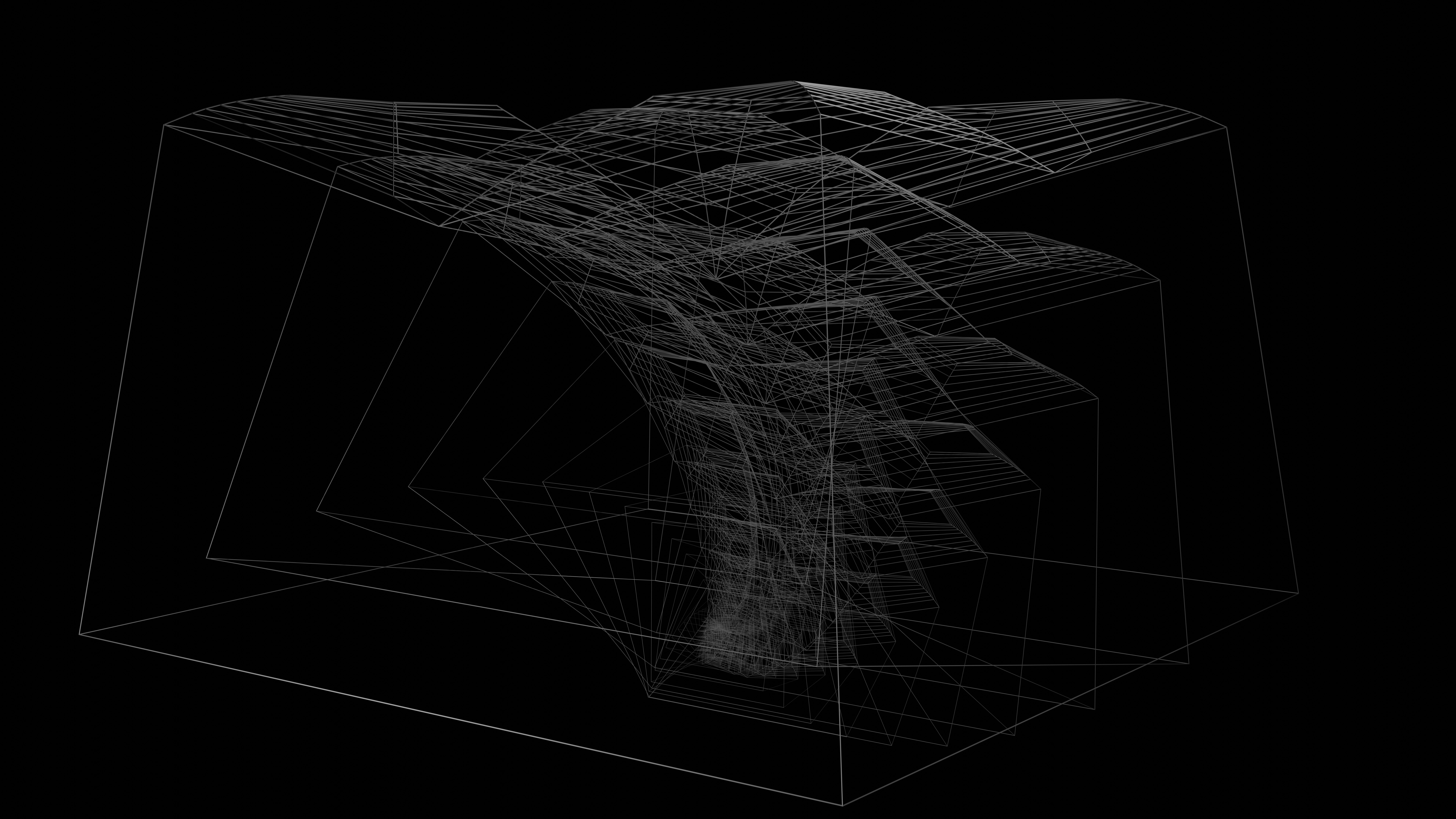
- 2D Files (DXF, DWG): 2D files are essential for 2D profiling processes like laser cutting and waterjet cutting. A DXF (Drawing Exchange Format) file is the industry standard for providing the flat pattern of the part—the unfolded 2D shape before it's bent. While some shops accept DWG files, DXF is more universally compatible across different software systems, making it the safer choice.
When preparing files, ensure they are "clean," meaning they consist of continuous lines with no gaps or overlapping contours, and are scaled 1:1 to the final part size.
Detailing Tolerances, Finishes, and Assembly Notes
A 3D model shows the shape, but it doesn't tell the whole story. Critical manufacturing information must be communicated through annotations on a 2D drawing (often sent as a PDF) that accompanies the CAD files.
- Tolerances: Tolerances define the acceptable deviation from a specified dimension. While modern equipment is highly precise, applying unnecessarily tight tolerances everywhere increases cost. Standard tolerances for sheet metal are often around ±0.010" to ±0.020" (±0.25 mm to ±0.5 mm). Tighter tolerances should be reserved only for critical features where fit and alignment are paramount, such as hole locations or mating surfaces. Always specify bend angle tolerances as well, which are typically ±1 degree.
- Finishes: The required surface finish should be clearly called out. This could include powder coating, anodizing, plating, or a specific grain direction for a brushed finish. Vague instructions can lead to a finish that doesn't meet your cosmetic or functional requirements. Specify the exact type, color (using a standard like a RAL code), and any required surface preparation.
- Assembly Notes: If the prototype is an assembly of multiple parts, your drawing must provide clear instructions. This includes detailing welding locations, specifying fastener types (like PEM inserts or rivets), and providing an exploded view to show how the parts fit together. Every piece of hardware should be included in a Bill of Materials (BOM).
By providing this comprehensive package of information, you empower the sheet metal factory to produce your prototype accurately and efficiently on the first attempt.
Key Design Considerations for Your Sheet Metal Factory Prototype
The design phase is where your prototype's success is truly determined. Thoughtful design choices at this stage have a ripple effect, influencing everything from manufacturability and cost to the final product's durability and performance. It's about moving beyond aesthetics and considering the physical realities of turning a flat sheet of metal into a functional three-dimensional part. Two pillars of this phase are material selection and the application of Design for Manufacturability (DFM) principles.
Material Selection: The Backbone of Your Sheet Metal Factory Product
The material you choose is the literal foundation of your part. This single decision affects strength, weight, corrosion resistance, thermal conductivity, appearance, and, crucially, cost. Choosing the wrong material can lead to critical failures, such as cracking during forming or rapid corrosion in the field.
Understanding Different Metals and Their Properties
The most common materials in sheet metal fabrication each offer a unique balance of properties. Understanding these differences is key to making an informed choice.
Steel: Known for its strength, durability, and versatility, steel is a popular and cost-effective choice.
- Mild Steel (Low-Carbon Steel): This is a cost-effective and highly formable option, ideal for structural components and applications where it will be protected by a coating, like powder coating. However, it has low corrosion resistance on its own.
- Stainless Steel: Containing a high chromium content (at least 10.5%), stainless steel offers excellent resistance to rust and corrosion, making it perfect for medical equipment, kitchen appliances, and parts exposed to moisture. Grades like 304 are a common choice for their balance of formability and resistance, while 316 is preferred for harsh marine or chemical environments. It is generally heavier and stronger than aluminum.
- Galvanized Steel: This is mild steel coated with a layer of zinc to provide corrosion protection. It's often used for outdoor enclosures, roofing, and automotive parts.
Aluminum: Aluminum's primary advantages are its light weight and natural corrosion resistance. This makes it a go-to material for aerospace, automotive, and electronics industries where weight is a critical factor.
- 5052-H32: This alloy offers a great combination of good formability and high corrosion resistance, making it suitable for electronic chassis and tanks.
- 6061-T6: A structural alloy that is stronger than 5052 but less formable. It's often used in applications like aircraft structures where strength is critical, but designers must be cautious as welding can reduce its strength.
Other Metals:
- Brass: This alloy of copper and zinc is often chosen for its acoustic properties and aesthetic golden appearance, making it great for decorative fittings and musical instruments. It offers good strength and corrosion resistance.
- Copper: Known for its excellent electrical conductivity, copper is essential in electrical applications. It's also malleable and corrosion-resistant.
Here's a comparative overview:
| Material | Key Properties | Common Applications | Relative Cost |
|---|---|---|---|
| Mild Steel | High strength, good weldability, formable | Structural frames, indoor brackets, machinery | Low |
| Stainless Steel | Excellent corrosion resistance, hygienic, durable | Food equipment, medical devices, outdoor parts | High |
| Aluminum | Lightweight, naturally corrosion-resistant, good conductivity | Aerospace parts, electronic enclosures, automotive | Moderate |
| Galvanized Steel | Good corrosion resistance, durable | Outdoor furniture, construction, automotive | Low-Moderate |
| Brass | Decorative, good acoustic properties, low friction | Fittings, musical instruments, decorative hardware | High |
Impact of Material Choice on Manufacturability and Cost
The choice of material directly influences both the ease and cost of manufacturing. Harder materials like stainless steel require more force to cut and bend, which can slow down production and increase wear on tooling. In contrast, softer materials like aluminum are easier to machine and form.
Material thickness is another major cost driver. Thicker sheets are not only more expensive to purchase but also require more energy and time to process. For instance, processing a 1.2 mm thick stainless steel sheet can be significantly more expensive than an 0.8 mm mild steel sheet due to the increased machine load and slower cutting speeds. A strategic approach involves selecting the thinnest material that still meets the project's strength and durability requirements, thereby optimizing for cost without compromising performance.
Applying Design for Manufacturability (DFM) Principles
Design for Manufacturability (DFM) is a proactive approach where parts are designed to be as easy and efficient to manufacture as possible. Applying DFM principles to your sheet metal prototype can drastically reduce costs, improve quality, and shorten lead times. It involves designing with the fabrication process in mind.
Avoiding Common Design Pitfalls in a Sheet Metal Context
Many design errors in sheet metal stem from a lack of understanding of how the material behaves during fabrication. Here are some common pitfalls to avoid:
- Features Too Close to Bends: Placing holes, slots, or other cutouts too close to a bend line is a frequent mistake. The material in this area is under intense stress during forming, which can cause the features to deform, stretch into an oval shape, or even tear. This leads to issues with fastener alignment and can compromise the part's structural integrity.
- Impractically Sharp Bends: A true 90-degree sharp internal corner is physically impossible in sheet metal bending. Every bend has an internal radius. Designing with an inside bend radius that is at least equal to the material's thickness is a good rule of thumb to prevent cracking, especially in less ductile materials.
- Complex Geometries and Unnecessary Bends: Every bend adds a step to the manufacturing process and introduces another potential point of variation. Simplify your design by minimizing the number of bends and using standard angles like 90 or 45 degrees whenever possible.

Optimizing Bends, Cuts, and Fastener Locations
Strategic placement and design of features are at the heart of DFM.
- Bends and Reliefs: When a bend doesn't extend across the entire part or meets another flange, stress can build up at the corners and cause tearing. To prevent this, designers should incorporate bend reliefs. These are small cuts made at the edge of a flange that allow the material to bend without distorting adjacent areas. A relief cut should typically be at least as wide as the material thickness and slightly deeper than the bend radius.
- Holes and Slots: As a rule, holes should be placed at a distance of at least 2.5 times the material thickness plus the bend radius away from a bend. For slots, this distance should be even greater, around 4 times the thickness plus the radius. To avoid bulging at the material's edge, holes should also be at least twice the material thickness away from any edge.
- Fasteners and Hardware: The placement of fasteners like screws and PEM inserts is critical for assembly. When using self-clinching hardware, ensure the material is compatible and within the recommended thickness range for that specific fastener. Misplacing fasteners can interfere with assembly, cause material deformation, or lead to joint failure. All these factors must be considered to ensure the final assembly is robust and easy to produce.
By thoughtfully considering these design principles, you can create a prototype that is not only functional but also optimized for a smooth and cost-effective transition to production.
Exploring Manufacturing Processes with Your Sheet metal Factory Partner
Once your design is refined, the next step is to bring it to life. This involves a close partnership with your sheet metal factory to select and execute the right manufacturing processes. The methods used to cut, form, and finish your prototype will directly influence its accuracy, appearance, and functional performance. It's not just about creating a shape; it's about employing a series of precise operations to build a part that meets your exact specifications.
Common Prototyping Methods Utilized by a Sheet Metal Factory
Modern sheet metal factories use a range of computer-controlled (CNC) equipment to rapidly and accurately fabricate prototypes from CAD data. These tool-less methods are ideal for low-volume runs, as they don't require the expensive and time-consuming creation of custom dies.
Laser Cutting, Punching, and Forming Techniques
The journey from a flat sheet to a 3D part primarily involves cutting and bending.
Laser Cutting: This is a fundamental technology in modern sheet metal prototyping. A high-powered laser beam, guided by a CNC system, melts or vaporizes the metal to create incredibly precise cuts with clean edges. It's highly versatile and can produce intricate contours and complex geometries that would be difficult or impossible with traditional tools. Because it's a non-contact process, there is no tool wear, ensuring consistent quality from the first part to the last. Its speed and accuracy make it ideal for quickly producing the 2D "flat patterns" that will later be bent.
Turret Punching: A CNC turret punch press uses a rotating turret that holds dozens of standard punch-and-die tools. The machine rapidly positions the sheet metal and uses these tools to punch out holes, slots, and other shapes. For shapes that don't match a standard tool, the machine can "nibble" the contour with a series of overlapping punches. Turret punching is extremely fast and cost-effective for parts with many standard holes or repetitive features. It's an excellent choice for prototyping as it avoids the need for specialized stamping dies.
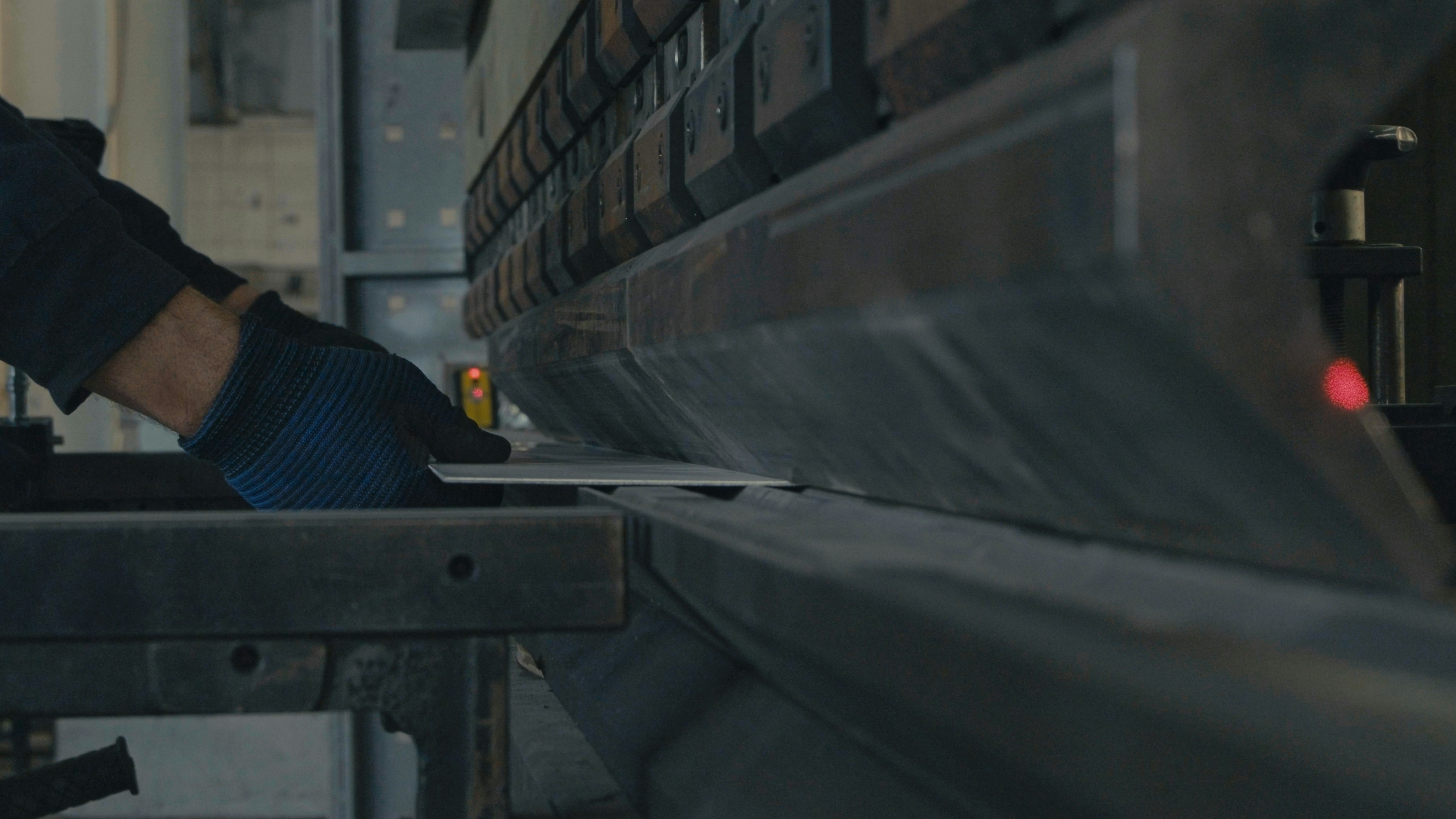
Press Brake Forming: This is the core process for bending sheet metal. The flat, cut part is placed on a die in a press brake machine. A punch then descends with controlled force, bending the metal to a specific angle. Modern CNC press brakes can create a series of complex bends with high precision and repeatability. Skilled operators and accurate programming are essential to account for material properties like "springback"—the tendency of the metal to partially return to its original shape after bending.
Advanced Techniques for Complex Geometries
For parts with non-linear or highly complex shapes, more advanced forming techniques may be necessary.
Hydroforming: This process uses high-pressure hydraulic fluid to press a sheet of metal into a die. Unlike a traditional rigid punch, the fluid exerts uniform pressure across the entire surface of the workpiece. This allows for the creation of complex, irregular shapes with deep draws and smooth curves without welds or seams. It minimizes localized stress and reduces the risk of material tearing or wrinkling, making it ideal for forming components in the aerospace and automotive industries.
Stamping and Coining: While more common in high-volume production due to the need for custom dies, some stamping can be used in prototyping. Coining is a high-pressure bending process where the punch presses the material so forcefully into the die that it eliminates springback almost entirely, resulting in extremely precise angles.
Considering Secondary Operations and Finishing Options
Fabrication rarely ends with cutting and bending. Secondary operations are the crucial final steps that turn a formed part into a finished product. These processes add functional features, join components, and apply protective or cosmetic surfaces.
Welding, Assembly, and Fastening Considerations
Most complex products are assemblies of multiple sheet metal parts. Bringing these components together requires careful consideration of joining methods.
- Welding: Welding creates a strong, permanent bond by fusing metal parts together with heat. Common techniques include MIG (Metal Inert Gas) welding, which is fast and economical for structural joints, and TIG (Tungsten Inert Gas) welding, which offers high precision and a clean appearance, making it ideal for visible seams on materials like stainless steel or aluminum. However, welding can introduce heat distortion, especially in thin materials, which your design must account for.
- Fastening: Mechanical fasteners are often used for assemblies that may need to be taken apart for service or access. This includes using standard hardware like bolts and screws, often in conjunction with threaded PEM inserts that are pressed into the sheet metal to provide strong, reusable threads. Rivets are another option for creating strong, permanent joints without the heat of welding. The choice of fastener depends on load requirements, serviceability, and cost.
Surface Treatments and Coatings for Enhanced Durability
Surface finishing is the final step and serves both aesthetic and functional purposes, protecting the part from corrosion and wear while providing the desired appearance.
- Powder Coating: This process involves electrostatically applying a dry polymer powder to the metal part, which is then cured under heat to form a hard, durable finish. It is available in a vast array of colors and textures and provides excellent resistance to chipping, scratching, and corrosion. Powder coating works on nearly all metals, including steel, aluminum, and stainless steel.
- Anodizing: Primarily used for aluminum, anodizing is an electrochemical process that grows a hard, durable oxide layer on the metal's surface. This layer is integral to the metal, so it won't chip or peel. It provides excellent corrosion and wear resistance. While color options are more limited than powder coating, it results in a thin, precise coating that doesn't significantly alter the part's dimensions, making it ideal for tight-tolerance components.
- Other Finishes: Additional options include painting for a wide color selection, plating with metals like zinc or chrome for corrosion resistance and a specific look, and brushing or polishing to create a decorative satin or reflective finish.
Choosing the right combination of manufacturing processes and finishes in collaboration with your factory partner is essential for producing a prototype that is both a successful test of your design and a high-quality representation of your final product.
Fostering Effective Collaboration with Your Sheet Metal Factory
Even the most meticulously planned project can falter without strong collaboration between you and your sheet metal factory. Think of your fabricator not just as a service provider, but as an extension of your design team. Their hands-on expertise is an invaluable resource. Effective collaboration is built on a foundation of clear communication, mutual respect, and a shared commitment to quality. This partnership is what transforms a good design into a great final product, ensuring that potential issues are caught early and the prototyping process runs smoothly and efficiently.
The Importance of Clear and Consistent Communication
Clear, proactive, and consistent communication is the lifeblood of a successful fabrication project. Misunderstandings are the primary cause of delays, costly mistakes, and frustration. Establishing a dedicated communication channel, whether through regular meetings, emails, or a designated point of contact, ensures that information flows freely and promptly. Engaging with your fabrication partner early in the design process is vital; their initial feedback can help make your vision a reality with fewer obstacles.
Providing Detailed Instructions and Timely Feedback
The instructions you provide are the blueprint for your prototype. Vague or incomplete information leaves your fabricator guessing, which can lead to a part that doesn't meet your expectations. When you submit your design, ensure you provide detailed drawings and specifications.
Once you receive the prototype, providing timely and constructive feedback is equally crucial. Instead of simply stating "this doesn't work," offer specific insights. For example, explain why it doesn't work: "The mounting holes are misaligned by 2mm, which prevents it from fitting into the main assembly," or "This edge is sharper than expected and poses a safety concern." This type of actionable feedback gives the fabricator clear direction for revisions. Using methods like the "hamburger method"—starting with a positive point, addressing the issue, and ending with another positive—can make the feedback more receptive and maintain a good working relationship.
Asking the Right Questions for Clarity and Understanding
Communication is a two-way street. Don’t hesitate to ask your fabricator questions to tap into their expertise. Here are some key questions to ask:
- About Design for Manufacturability (DFM): "Are there any features in my design that you foresee being difficult or costly to manufacture? Can you suggest any modifications to improve efficiency?"
- About Materials: "Based on my application, is the material I've selected the best choice, or would you recommend an alternative for better performance or cost savings?"
- About Tolerances: "Are the tolerances I've specified achievable with your standard processes, or will they require special handling and additional cost?"
- About the Process: "What does your quality assurance process look like? At what stages do you perform inspections?"
Asking these questions demonstrates that you value their input and helps build a collaborative partnership, ultimately leading to a better product.
Ensuring Quality Assurance and Inspection Standards
Quality assurance (QA) isn't just a final step; it's an iterative process that should be integrated throughout the fabrication journey. A robust QA plan ensures that the final prototype is free of defects and meets all design specifications. This involves everything from inspecting raw materials to verifying the final dimensions of the finished part.
Verifying Accuracy and Meeting Specified Tolerances
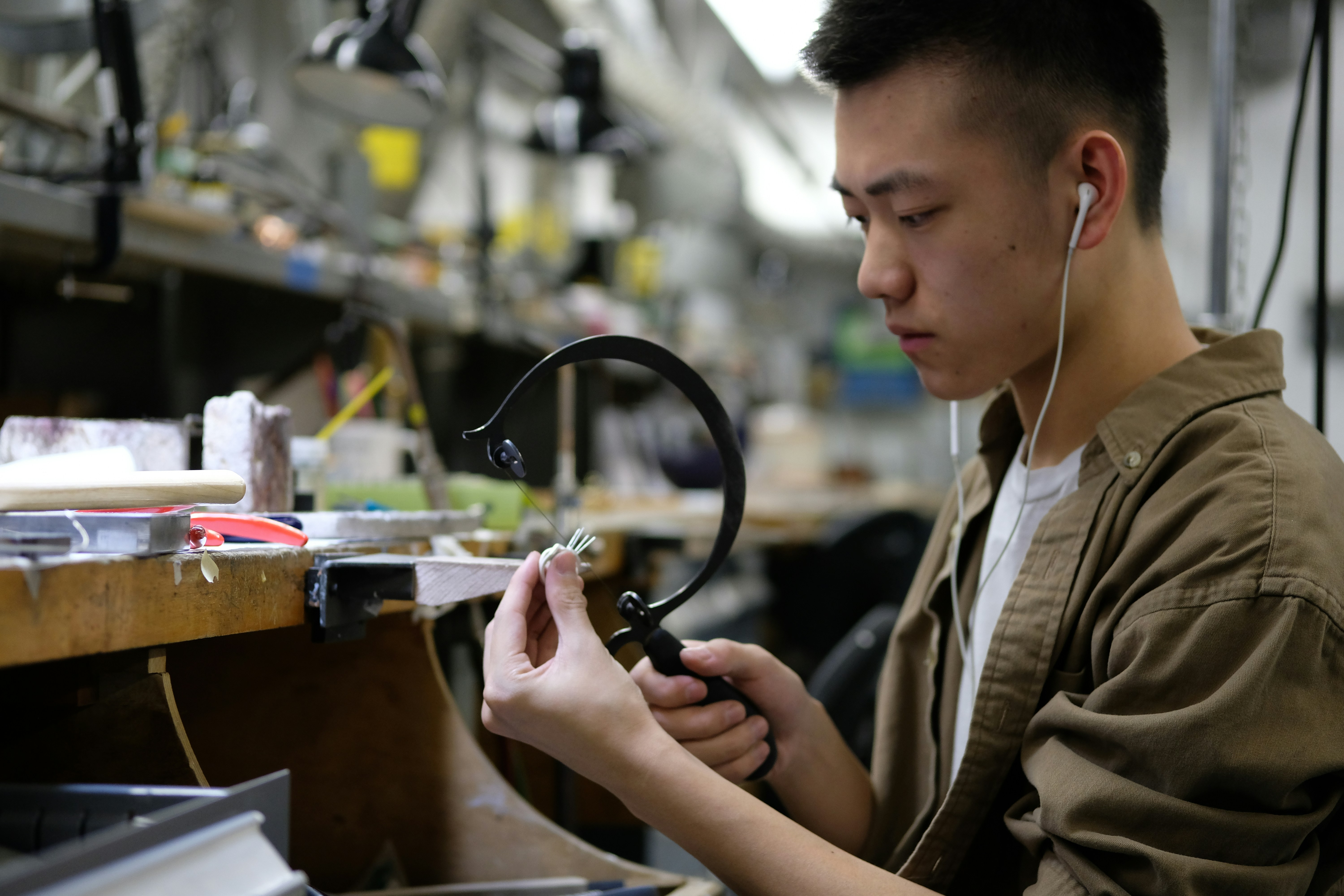
Verifying the dimensional accuracy of the prototype is one of the most critical inspection tasks. This ensures that the part will fit and function as intended. Fabricators use a variety of tools for this purpose:
- Manual Measuring Tools: For many dimensions, traditional tools like digital calipers, micrometers, and angle gauges are sufficient. They are excellent for quick checks of straightforward features like lengths, hole-to-hole distances, and bend angles.
- Coordinate Measuring Machines (CMMs): For complex geometries or parts requiring very high precision, a CMM is the gold standard. A CMM uses a probe to touch points on the part's surface, creating a 3D map of its geometry that can be compared directly to the CAD model. This method is far more precise than manual measurement for verifying complex profiles, flatness, and GD&T (Geometric Dimensioning and Tolerancing) callouts.
- Laser Scanning: This non-contact method captures thousands of data points in seconds to create a precise digital profile of the part. It is excellent for comparing a part's overall shape to the CAD file and quickly identifying deviations, warping, or distortion.
It's important to work with your fabricator to determine the appropriate inspection method for your part's requirements, as tighter tolerances and more advanced inspection methods can increase costs.
Conducting Post-Prototyping Review and Planning Next Steps
The prototype is not the end goal; it's a learning tool. Once you've inspected the part and completed functional testing, it's time for a post-prototyping review. This is a critical meeting with your team and often your fabricator to discuss what was learned.
During this review, gather all feedback, test results, and inspection reports. The key questions to answer are:
- Did the prototype meet all design objectives?
- What worked well, and what failed?
- What design changes are needed for the next iteration?
- Is the design ready for batch production, or does it require another prototyping cycle?
This review process is what makes prototyping so valuable. It allows you to systematically refine your design based on real-world data. After analyzing the results, you can confidently plan the next steps, whether that’s making minor tweaks for a second prototype or giving the green light for low-volume production because the design has been successfully validated.
Conclusion
Successfully bringing a sheet metal product from an initial CAD design to a production-ready status is a testament to meticulous planning, thoughtful design, and informed decision-making throughout the prototyping phase. It's a journey that balances creative vision with the practical realities of manufacturing.
By focusing on these key considerations – from understanding your project's objectives and preparing your files, to selecting the right materials and processes, and fostering open communication with your chosen sheet metal factory – we can navigate the prototyping journey with confidence and efficiency. This holistic approach ensures that each step builds purposefully on the last, transforming an idea into a tangible, high-quality component.
We hope this guide empowers you to make your next sheet metal prototyping project a smooth and successful endeavor, leading to high-quality, production-ready parts that meet your expectations and beyond. Happy prototyping!
Frequently Asked Questions (FAQs)
1. What is the main purpose of sheet metal prototyping?
The primary purpose of sheet metal prototyping is to create a physical, functional model of a design before committing to the high costs and long lead times of mass production tooling. It serves several key functions: to validate the form, fit, and function of a design; to identify and correct design flaws early; to test material choices and structural integrity; and to provide a tangible product for stakeholder feedback and marketing purposes. Ultimately, prototyping minimizes risk and saves costs by allowing for rapid, low-cost iterations.
2. How much does a typical sheet metal prototype cost?
The cost of a sheet metal prototype can vary dramatically, ranging from a few hundred to several thousand dollars. The main factors that influence the cost are part complexity (number of bends, cuts, and features), material type and thickness (stainless steel is typically more expensive than mild steel), the number of secondary operations (welding, assembly), required surface finishes (powder coating, anodizing), and the quantity of prototypes ordered. A simple bracket made from mild steel will be on the lower end of the cost spectrum, while a complex, multi-part enclosure made from aluminum with an anodized finish will be significantly more expensive.
3. What is the fastest way to get a sheet metal prototype?
The fastest way to get a sheet metal prototype is to thoroughly prepare your design files and work with a fabricator that specializes in rapid prototyping. This means providing clean, manufacturing-ready CAD files (including 3D STEP and 2D DXF flat patterns) with clear instructions for tolerances, materials, and finishes. Processes like laser cutting and CNC press braking are inherently fast and ideal for quick-turn prototypes. Minimizing complexity, using standard materials and gauges, and forgoing complex finishes if they are not essential for initial testing will also significantly speed up the turnaround time.
4. What are the most common mistakes to avoid in sheet metal prototype design?
The most common mistakes often stem from not adhering to Design for Manufacturability (DFM) principles. These include:
- Placing features too close to bends: This causes distortion and deformation of holes and slots.
- Designing with an inside bend radius that is too small: Forgetting that every bend has a radius can lead to material cracking. A good rule of thumb is to have an inside bend radius at least equal to the material thickness.
- Over-tolerancing: Applying unnecessarily tight tolerances to non-critical features increases cost and manufacturing complexity.
- Ignoring material properties: Choosing a material that is not suitable for the required forming operations (e.g., a less ductile aluminum alloy for a tight bend) can lead to part failure.
5. How do I transition from a successful prototype to full production?
Once you have a successful prototype that has been thoroughly tested and validated, the next step is to plan for production with your manufacturing partner. This involves a final review of the design to identify any last-minute optimizations for cost-efficiency at higher volumes. You will need to finalize the Bill of Materials (BOM), confirm tooling requirements (for processes like stamping, if applicable), and establish quality control standards for the production run. Clear communication with your factory is key to ensure a smooth handoff from the prototyping phase to batch or mass production, ensuring the quality and design intent of your prototype is maintained at scale.